Before I go too far down the road for this plan, I wanted to run it by you guys.
I came up with an old CB and had a couple SS whips hanging around so, time to play.
I'm a total Newb but, have been reading a bit and came up with this hair brained plan.
1/2 wave, center fed, vertical dipole w/ feedline @ 90deg.
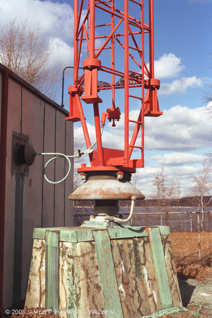
My space is constrained and a high mast is not an option. In reading about the radiation patterns, the straight vertical may not produce optimal results@ my location but, would surely be 'acceptable'. Then I read more and found some 'bent' designs so, I came up with a possible a mount.
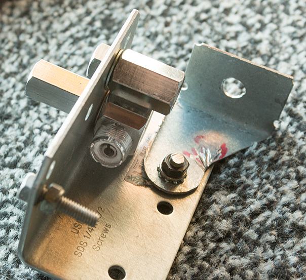
The initial design was for the straight vertical (as evidenced by the two opposing mounts on the top flat of the bracket). Then, I added the 'swinger' bottom - crudely marked for 90, 60, 45, and 30 deg angles. (will add a second screw hole to 'lock' it into the various positions and test for strength)
So - this is an article that i'm currently a bit interested in (qsl link below).
With the angle change of the elements comes a change in the length. I plan to accommodate for that by using some 3/8 x 24 threaded rod to lengthen as necessary based on the angle.
Link - Center-fed Vertical L-dipoles
Does this overall mount plan seem sound?? I could use the change in radiation pattern, utilizing the more 'tailored' radiation pattern as my antenna location isn't perfectly suited to a straight vertical.
I'd also assume that the length offset produced by the 'swinging' leg (rough offset from the pivot bolt to the mount [empty hole in pic]) would have to be figured into the length of that leg. True??
Am I going down the right path?
Thanks - I'm hoping to only have to get on the roof 1/2 a dozen times to tune it.
")
ETA: found a better link - cleaned up post based on new info.
I came up with an old CB and had a couple SS whips hanging around so, time to play.
I'm a total Newb but, have been reading a bit and came up with this hair brained plan.
1/2 wave, center fed, vertical dipole w/ feedline @ 90deg.
My space is constrained and a high mast is not an option. In reading about the radiation patterns, the straight vertical may not produce optimal results@ my location but, would surely be 'acceptable'. Then I read more and found some 'bent' designs so, I came up with a possible a mount.
The initial design was for the straight vertical (as evidenced by the two opposing mounts on the top flat of the bracket). Then, I added the 'swinger' bottom - crudely marked for 90, 60, 45, and 30 deg angles. (will add a second screw hole to 'lock' it into the various positions and test for strength)
So - this is an article that i'm currently a bit interested in (qsl link below).
With the angle change of the elements comes a change in the length. I plan to accommodate for that by using some 3/8 x 24 threaded rod to lengthen as necessary based on the angle.
Link - Center-fed Vertical L-dipoles
Does this overall mount plan seem sound?? I could use the change in radiation pattern, utilizing the more 'tailored' radiation pattern as my antenna location isn't perfectly suited to a straight vertical.
I'd also assume that the length offset produced by the 'swinging' leg (rough offset from the pivot bolt to the mount [empty hole in pic]) would have to be figured into the length of that leg. True??
Am I going down the right path?
Thanks - I'm hoping to only have to get on the roof 1/2 a dozen times to tune it.
ETA: found a better link - cleaned up post based on new info.
Last edited: