• If you enjoy the forum please consider supporting it by signing up for a NES Membership  The benefits pay for the membership many times over.

Any Electronics Repair guys out there to help with finding parts for a power supply?

Gator9329

That Guy
NES Member
Joined
Dec 17, 2009
Messages
5,094
Likes
3,984
Location
Burlington
Feedback: 18 / 0 / 0
View attachment 36063View attachment 36064I have a TRIPP-LITE PR-40 power supply that I need to find a replacement rectifier for. It has a strange setup that uses a full wave rectifier. At least that is what I think it is. The rectifier has the usual two AC inputs , but the outputs are both positive. Normally it would have a pos and neg output. It looks to have a center tapped transformer. That makes me think It is a full wave. I can't find the part anywhere. YouDoIt had no idea. I need someone who knows electronics to help out. The company will not give out parts or schematics.
Thanks
 
Last edited:
Without seeing pictures or a schematic, it sounds like an AC to DC rectification circuit. The equipment that I work on uses this type of circuit all the time in order to transform 120 or 240 volts AC down to nominal 12 volts DC for control circuits. The four-diode bridge rectifier alters the AC to DC and the transformer steps down the 120 volts to nominal 12 volts. You end up by inputting 120 volts AC and outputting 12 volts DC. This avoids a pulsed DC output and gives you a relatively clean 12 volts DC on the cheap.
 
anyone got a file cabinet of old SAM's Photofacts?

(actually they are out there online in .pdf)
 
I order my parts from digikey usually. They seem to be well priced and I get the parts fast.

Sent from my SCH-I535 using Tapatalk 2
 
I updated the original post with pictures. You can see that the two blue wires are ac input from the transformer.the two red wires both are POSITIVE output. I could not find a rectifier like it. Has anyone seen anything like this?
 
This is not a standard rectifier that most p.supplies use.It was explained to me that a half wave rectifier has a negative and a positive output. I need a rectifier that has TWO POSITIVE OUTPUTS. The link posted shows in the data sheet that it has - and + . I may not be reading it right. Let me know if I am not. I really need this part.
 
What makes you think you have 2 positive outputs?

~ is the AC connection
+ is DC

Other side will have

~ for the other leg of AC
and - for the DC

The colors of the cables should never be trusted. Just because they are red, does not make them positive.
 
because the unit is marked with Two + signs. when I meter it, they both are positive voltage. The negative comes from the center tap of the transformer.
 
View attachment 36120

I saw that thread. Those people were also assuming that it was just a bridge rectifier. They were wrong. This absoloutly does not have a negative output from the rectifier. It has been checked by two people . these positive leads go into a cleanup circuit that regulates the voltage to the output lugs. The negative comes from the transformer and into this regulator board. notice the thick 10 awg black wire that comes from the transformer and the two thick 10 awg red wires that come from the rectifier. the 12awg red wire on the right goes to output lug. Neg comes off the back of the board and leads to neg output lug.
 
Last edited:
View attachment 36120

I saw that thread. Those people were also assuming that it was just a bridge rectifier. They were wrong. This absoloutly does not have a negative output from the rectifier. It has been checked by two people . these positive leads go into a cleanup circuit that regulates the voltage to the output lugs. The negative comes from the transformer and into this regulator board. notice the thick 10 awg black wire that comes from the transformer and the two thick 10 awg red wires that come from the rectifier. the 12awg red wire on the right goes to output lug. Neg comes off the back of the board and leads to neg output lug.


Full-wave rectification can be achieved either through a four diode matrix or through two diodes and a transformer. It sounds like you have the latter. Maybe you really have two separate diode configurations in a common package.
 
If you have not actually identified the configuration of the diode block, how do you know it is bad?


There are two of these in the power supply. One works, the other when hooked up blows the 10 amp main fuse. when I ohm it out there is a direct short between all posts in all directions on the bad one. on other rectifier i only get readings in only one direction.
 
There are two of these in the power supply. One works, the other when hooked up blows the 10 amp main fuse. when I ohm it out there is a direct short between all posts in all directions on the bad one. on other rectifier i only get readings in only one direction.


So, map out the matrix on the good one and compare it to the diode configuration in the 35 amp Astron supply. If it is the same configuration, order the bridge rectifier that is used in the Astron (or make your own out of 4 appropriate diodes).
 
So, map out the matrix on the good one and compare it to the diode configuration in the 35 amp Astron supply. If it is the same configuration, order the bridge rectifier that is used in the Astron (or make your own out of 4 appropriate diodes).
It's not a bridge rectifier in a Astron 35 amp supply. The diode block is configured as a full-wave rectifier. From what the OP is posting, it sounds like a similar if not the same thing in his box.
 
There are two of these in the power supply. One works, the other when hooked up blows the 10 amp main fuse. when I ohm it out there is a direct short between all posts in all directions on the bad one. on other rectifier i only get readings in only one direction.
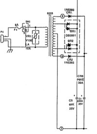
Good troubleshooting. Ohm out the two wires that connect to the + terminals, are they 0 ohms? I'm assuming this is a full wave rectifier like in a Astron 35. In this diagram, CR1 and CR2 form one full-wave rectifier, and the diode block DB3501 form another. The center tap of the transformer is the negative side, and the cathodes of the diodes are tied together for the positive output.

Seems like you could replace the "special" part with two beefy diodes if this is how it's wired.

RS35m_partial.jpg
 
I ended up buying a rectifier that has two ac inputs and + and - outputs . I powered the ac in and only hooked the positive up and left the other neg terminal empty (when i tried the other line to the output it blew the fuse- obviously). Looking at the regulating board that the + outputs go to, the two red wires do go to a common pont. They are linked by the board. I powered it up and I got the 13.8 volts the unit is rated for. I have not put it under load yet. I hope it will work for my needs. If I can get the same part that broke made for another supply i'm in.
Thanks again for all your work on this.
 
If there is room on the heat sink, you could get two regular bridge rectifiers, make jumper wires for additional AC inputs and attach those wires to the positive outputs of each rectifier.
 
It's not a bridge rectifier in a Astron 35 amp supply. The diode block is configured as a full-wave rectifier. From what the OP is posting, it sounds like a similar if not the same thing in his box.

Simple slip of terminology. I think from the schematic I posted, everyone knows what I'm talking about.
 
I've emailed the OP with a copy of the Tripplite schematic for the PR-60D, the bigger sibling to the 40. That should get him going. He can post it here, if he wishes, for further discussion. The Tripplite has a cleaner setup from the transformer secondary than the Astron that I posted about earlier.
 
I've emailed the OP with a copy of the Tripplite schematic for the PR-60D, the bigger sibling to the 40. That should get him going. He can post it here, if he wishes, for further discussion. The Tripplite has a cleaner setup from the transformer secondary than the Astron that I posted about earlier.
There's only so much electronics repair that can be completed with a keyboard [laugh]
 
Back
Top Bottom